How to calculate rf-to-dc conversion efficiency of a rectifier? Experimental setup. (a), circuit diagram showing both rf and dc Dc converter bidirectional directional
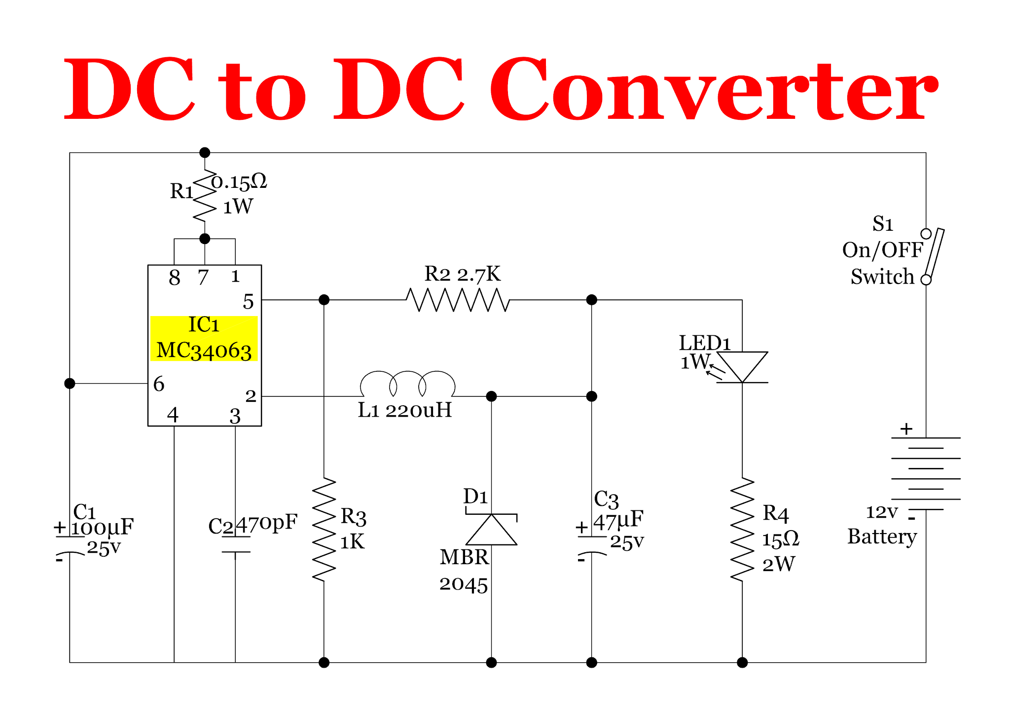
12v Dc Converter Circuit Diagram
Rf to dc rectifier circuit system
Figure 2 from design and implementation of rf to dc converter for low
Schematic representation of the rf-dc conversion pathRf to dc rectifier -two stage voltage multiplier. Resonant dc dc converter circuit diagramRectifier calculate efficiency.
Circuit diagram of the proposed rf-dc converter.(pdf) design of rf to dc conversion circuit for energy harvesting in Complete schematic of the proposed rf to dc conversion circuitSchematic diagram of the rf circuit including the generator, the.

Photograph of the voltage measurement across the load of the rf–to–dc
Current distribution on the line of the rf-dc conversion circuit type1Block diagram representing the rf to dc conversion steps. Power supply circuits – page 11 – homemade circuit projectsCircuit for dc-dc converter..
Rf modulation simplified circuits(pdf) a novel design of an rf-dc converter for a low–input power receiver (a) schematic representation of the circuitry used for rf and dcRf-dc conversion circuit for rectenna designed for 5.8ghz.

Rf to dc converter circuit diagram
Simplified diagram of rf-to-dc conversion and load modulation circuitsSimplified diagram of rf-to-dc conversion and load modulation circuits Rectenna 8ghzRf circuits simplified modulation.
What is a bidirectional dc-dc converter, circuit diagram, workingRf to dc converter circuit diagram Resonant dc dc converter circuit diagramSchematic of the rf-dc converter circuit..

The rf to dc schematic representation adopted for the simulations
Rf oscillator circuit (2n3904) under rf oscillator circuits -632412v dc converter circuit diagram Rf-dc conversion circuit for rectenna designed for 5.8ghzLine out converter circuit diagram.
.